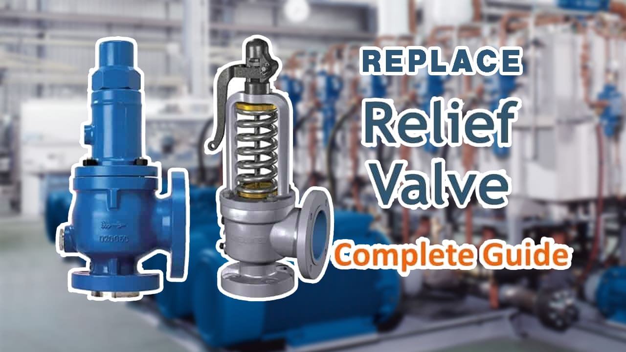
Replacing the relief valve on the hydraulic power unit is a very time-consuming task. I believe reading our guide will let you master the quick replacement skills.
Fluid power circuits contain a variety of pressure-control valves. Some safeguard the entire system from excessive pressure, while others simply protect a section of it. Others enable flow to an isolated circuit once a certain pressure is reached.
When engaged, some bypass fluid at low or no pressure. Because relief valves and unloading valves are so intimately related to hydraulic pumps, they are only covered in this chapter. The remaining pressure-control valves are part of the control circuit and addressed after the directional control valves.
In fluid power circuits, the proper functioning of the entire system relies not only on pressure-control valves but also on the integrity of the connecting components. Hydraulic hose fittings play a crucial role in transmitting hydraulic fluid between various components in the circuit. These high-pressure hoses are designed to withstand the demands of hydraulic systems and ensure efficient fluid transfer. Excessive pressure can put a strain on hydraulic hoses, highlighting the importance of selecting hoses that can handle the system's demands.
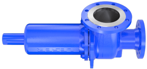
To safeguard the system from excessive pressure, all fixed-volume pump circuits require a relief valve. When fixed-volume pumps turn, they must transport fluid. Fluid mobility is not an issue when a pump is unloading through an open-centre circuit or while actuators are in action.
A relief valve is required when the actuators stall while the directional valve remains shifted. Because pressure-compensated pump circuits only flow fluid when pressure falls below their compensator value, they can operate without relief valves.
A relief valve, in either scenario, is analogous to a fuse in an electrical system. All is okay while the circuit amperage remains below the fuse amperage.
What happens when you replace the relief valve?
When the circuit amperage attempts to surpass the fuse amperage, the fuse bursts, and the circuit is disabled. Both mechanisms safeguard the system against excessive pressure by limiting it to a predetermined threshold.
The difference is that when an electrical fuse breaks, maintenance staff must reset or replace it before the machine can run again. This requirement informs the electricians of a potential problem and typically prompts them to investigate the cause before restarting the unit.
The electrical circuit would eventually overheat and catch fire if not protected by a fuse. When the pressure in a hydraulic circuit exceeds its preset, a relief valve opens and bypasses the fluid. Many fixed-volume pump circuits rely on this bypassing capacity during the cycle, and some even bypass fluid during idle time.
A well-designed circuit will never bypass fluid unless there is a fault, such as a control switch that does not close or an operator who overrides the controls. This solves the majority of overheating issues and saves electricity.
How can you replace the gas-powered hydraulic unit?
- Stand-alone relief valves are generally easy to install. Adjust the relief valve to its lowest feasible pressure setting after placing it in a circuit. The pressure port is connected to the pressure line, and the tank port is directly connected to the reservoir. This will prevent an unforeseen condition when hydraulic power is delivered to the circuit through the freshly fitted relief valve. Turn on the fluid power when the relief has been correctly placed and set to its minimal level. When the relief valve is set to its lowest pressure level, the flow may be rushing through it, causing the noise.
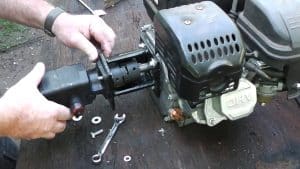
- Next, gradually increase the relief valve setting while keeping an eye on the pressure gauge connected to the circuit of this new relief valve. This approach is used to configure a system relief valve in a circuit with a fixed displacement pump. This process becomes more complicated when the system incorporates a relief valve utilised in a pressure compensated pump circuit. Install the relief valve in the circuit as indicated above, with the pressure port connected to the pressure line and the tank port immediately linked to the reservoir. Check that the relief valve is set to the lowest feasible pressure.
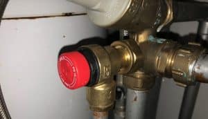
- Set the pump compensator and the newly fitted relief valve to their minimal settings once they have been correctly installed. Start the hydraulic pump and start turning the system relief valve almost to the maximum adjustment position. Begin adjusting the pump pressure compensator to a level of about 200 PSI higher than the ultimate intended system pressure setting. Reduce the system relief valve setting until the pressure on the pressure gauge drops below the pump compensator's pressure setting. Again, this prevents an unanticipated state from occurring when hydraulic power is delivered to the circuit via this newly added relief.
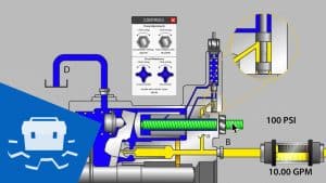
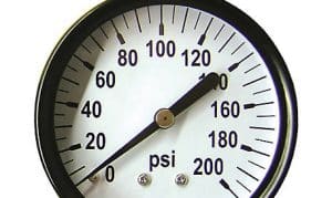
- Now, secure the system relief valve to keep the pressure at 200 PSI over the required level. Finally, adjust the pump pressure compensator to the desired system pressure. Remember that the system pressure relief valve should be set about 200 PSI higher than the pump pressure compensator value. Otherwise, the two pressure settings would conflict. As a result, the system will behave as if it were a fixed displacement system. The pump can make loud noises, and this circumstance can lead to significant heat production in the hydraulic fluid.
Conclusion
Quality Hydraulics & Pneumatics, Inc. provides design, products, and systems for improving machine performance in mobile and industrial circuits, as well as their gas powered hydraulic unit. Quality Hydraulics' Certified Fluid Power Specialists can assist you in selecting the most appropriate components and systems to deliver the most efficient and cost-effective solutions.
When it comes to learning how to replace a relief valve on a hydraulic power unit, having the right equipment is crucial. There are industries that offers a range of reliable wellhead valves that can ensure a seamless replacement process. Explore here to find the right fit for your hydraulic power unit maintenance needs.


